Vibration problem caused by a vibrating sieve machine installed on the fourth floor of the building!
This is a case in which vibration from a vibrating sieve installed on the 4th floor of a building was transmitted through the building, creating a poor working environment in a room on the lower floor. To what extent can the vibration be improved by using Yacmo's air-spring vibration isolators?
issue
A vibrating sieve is a device for sorting materials by size by placing them on a sieve (screen) with a certain mesh size and vibrating it to sort materials within a specified range and remove foreign matter, thereby improving product quality. On the other hand, because it moves very finely and at high speed, the machine inevitably generates large vibrations.
A steel-framed recycling plant had a vibrating sieve machine installed and used on the fourth floor. The third floor below the sieve machine was used as a workshop, and the client wanted to improve the working environment on the third floor when the vibrating sieve machine was in operation. Vibrating sieves are prone to vibration and low-frequency noise problems, and in this case, the fact that the sieve was installed on the fourth floor of a steel-frame structure, rather than on the earthen foundation of the first floor, was one of the factors causing the machine to generate significant vibration.
First, vibration measurements were taken to understand the current situation. The measurement locations are shown in Figure 1, and the results of vibration level measurements are shown in Figure 2 and Table 1. Regular vibrations were generated, with P-3 at 94 dB and P-4 at 79 dB on the 4th floor, where the sieves were installed. At P-2 on the 3rd floor, where the working environment was a problem this time, the vibration level was approximately 78 dB. How would you rate this 78 dB as a working environment? Plotting the frequency analysis data on the ISO-2631/2 curve (Figure 3), we found that the 12.5 Hz component exceeded the environmental factor of 8 (workplace standard), indicating the need to improve the vibration level. Therefore, it was decided that the target value of the vibration after the improvement should be less than the environmental coefficient of 8.
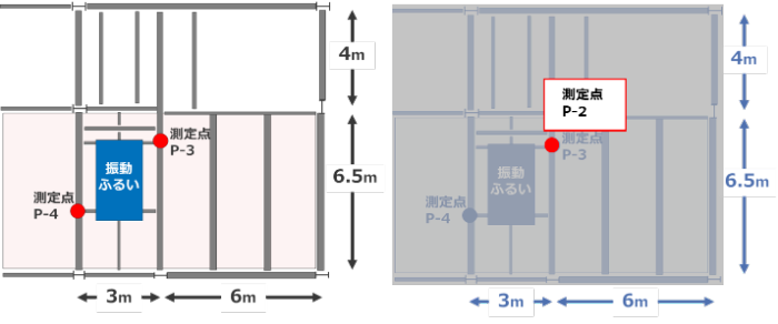
Figure 1. floor plan layout and measurement points (left: 4th floor, right: 3rd floor)
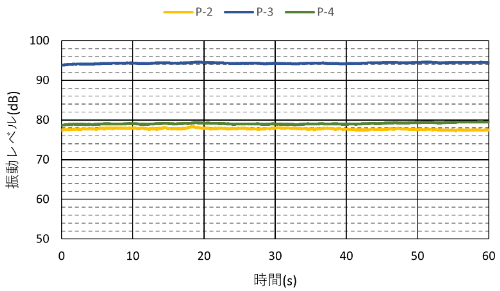
Figure 2: Vibration level time history waveforms (before countermeasures when the vibrating sieve machine was in operation)
Table 1. measurement results (before countermeasures, when the vibrating sieve machine was in operation)
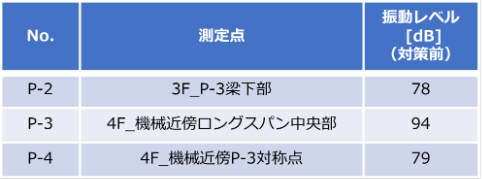
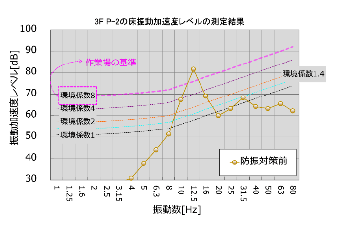
Figure 3.3 Results of floor vibration acceleration level frequency analysis for P-2 on 3F (before countermeasures) when the vibrating sieve machine was in operation
counter-measure
In order to examine the countermeasure method, we first analyzed the measurement results.
Frequency analysis of the vibration acceleration at each measurement point showed that 12.5 Hz was significant at all locations (Figure 4). Next, the vibrating sieve was stopped and the vibration acceleration measured by heel vibration near each measurement point was analyzed by FFT to determine the frequency at which the floor tends to shake (natural frequency) (Table 2). From this analysis, it was concluded that the natural frequency of the long-span beam at P-3: 4F contributed significantly to the 12.5Hz component that was generated when the vibration sieve was in operation, and that the vibration component resonantly amplified at this point was transmitted directly to 3F. Therefore, it was determined that it would be effective to reduce the 12.5-Hz component on the 4th floor, which is the source of the vibration.
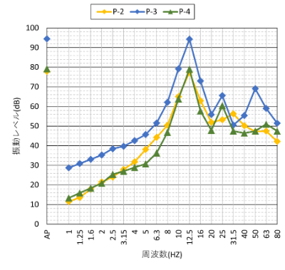
Figure 4: Results of floor vibration acceleration level frequency analysis at each measurement point (vibration sieve machine in operation, before countermeasures)
Table 2: Measurement results (floor heel excitation when vibrating sieve is stopped)

Considering the local situation, the following three measures were proposed.
- Reinforced beam rigidity
- Floor Damping with Vibration Damping Device TMD
- Vibration isolation by air spring
Regarding the first point, strengthening the beam rigidity, it is expected that the increased rigidity of the beams will reduce sway. However, it is necessary to increase the beam stiffness in order to increase rigidity, and it was determined that this would be impractical for post-construction.
The second method, using a vibration suppressor, was considered difficult because the machine's excitation force was so large (32,000 N x 2) that the vibration suppressor had to be several tons in size, which is quite large.
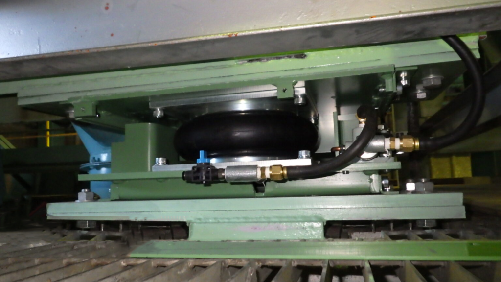
In order to obtain a sufficient effect at 12.5 Hz, the natural frequency of the vibration isolation system was designed to be approximately 2.5 Hz. Figure 5 and Table 3 show photographs and specifications of the air-spring vibration isolation system actually installed.
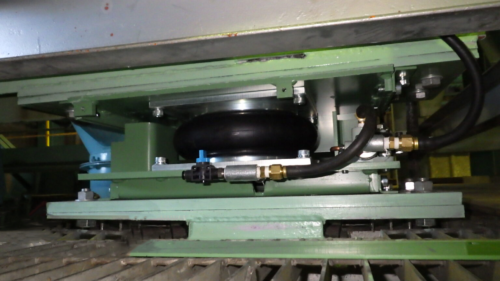
Figure 5: Appearance of air spring vibration isolator
Table 3: Basic Specifications of Vibration Isolators

result
After installation of the vibration isolators, vibration levels were measured to verify their effectiveness (Table 4, Figures 6-8).
Each measurement point was reduced by 8 to 12 dB, confirming that the vibration isolation effect was achieved.
The P-2 on 3F, which had been a problem, was again evaluated using ISO-2631/2, and the result was below the environmental coefficient of 8, clearing the target value (Figure 9). The vibration environment in the factory was greatly improved by this measure.
Table 4: Measurement results (before and after countermeasures when the vibrating sieve machine was in operation)


Figure 6. 1/3 oct. frequency analysis results (P-2: 3rd floor, bottom of P-3 beam)
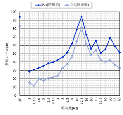
Figure 7. 1/3 oct. frequency analysis results (P-3: center of long span near machinery on 4th floor)
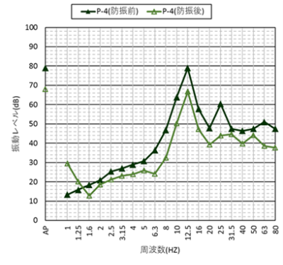
Figure 8. 1/3 oct. frequency analysis results (P-4: 4th floor, P-3 symmetry point near machine)
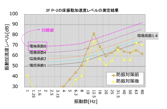
Figure 9. 3F P-2 floor vibration acceleration level frequency analysis results (comparison before and after countermeasures when the vibrating sieve machine is in operation)
Related Pages
- [Product Information] Air Springs
- Trivia] What is Vibration Isolation? Take measures to prevent machine vibration at the source of the vibration.
Related Content
- Technical Column] Countermeasures for Vibration Problems Caused by Production Equipment Machinery and Examples of Improvements
- Technical Column] Types and Features of Measures to Reduce Floor Swaying Caused by Walking and Machinery
- Webinar Video] Vibration Issues in Factories and Examples of Solutions
- Webinar Video] Countermeasures for Mechanical Vibration Problems Caused by Production Equipment and Examples of Improvements
